


Copyright © Breeze Co.,Ltd Introduction All rights reserved. Site Map
- +86571-56076080
- sales@memsmag.com
- Room B3250, 3rd Floor, Building 1 (North), No. 368 Liuhe Road, Puyan Street, Binjiang District, Hangzhou

Mai Xinminwei
Industrial Grade Inclinometer/Inclinometer Sensor
Product application scenarios and solutions
E. Subsidence and tilt monitoring The inclinometer and settlement sensor integrates a dynamic remote automated incline and settlement monitoring system, which can monitor the settlement, tilt, cracks and other data of buildings in real time and provide hazard avoidance suggestions, reducing manual measurement errors. |
Case 1: Automated monitoring of comprehensive pipe corridors on Jiangzhou Avenue and Tongjiang Avenue 1. Project Overview The total length of the underground comprehensive pipe gallery project of a certain avenue and Tongjiang Avenue in China is 6,400 meters (of which the avenue comprehensive pipe gallery is 4,635 meters long and the Tongjiang Avenue comprehensive pipe gallery is 1,765 meters long), with a double-cabin structure, the cabin is 3.1 meters high, the comprehensive cabin and the power cabin The width is 2.6 meters; there are four pipelines entering the corridor: electricity, water supply, reclaimed water, and communication; the project consists of standard sections, ventilation openings, feeding openings, pipeline leads, introductions, substations, inverted rainbow sections and other nodes. The main construction contents include overall engineering, structural engineering, fire protection system, drainage system, ventilation system, monitoring and alarm system, power supply and distribution system, etc.
Comprehensive pipe gallery This plan intends to carry out automated monitoring of the settlement, tilt and vibration of the comprehensive pipe corridors of Jiangzhou Avenue and Tongjiang Avenue. 2 Monitoring purpose and basis 2.1 Monitoring purpose The underground comprehensive pipe corridor is a structure that is shallowly buried underground. It is easily affected by the artificial environment and the natural environment, causing uneven settlement, tilt or vibration damage, resulting in structural fatigue damage, cracking, water seepage and other problems. Therefore, it is necessary to repair the pipe corridor The settlement, inclination angle and vibration are monitored. Automated monitoring has the advantages of high frequency, saving time and effort, and is an important measure to ensure the structural safety of pipe corridors. The municipal comprehensive pipe gallery is a long strip frame structure, so uneven settlement will have an extremely important impact on the pipe gallery: 1. Comprehensive pipe corridors are usually equipped with expansion joints at regular intervals. If uneven settlement occurs, the expansion joints will easily be dislocated and deformed. In severe cases, the waterstops will be pulled apart and cause leakage. 2. Cast-in-place pipe galleries are prone to construction cracks (side wall cracks, etc.). If uneven settlement occurs, it will affect the bearing capacity and durability of the structure and shorten the service life of the structure. 3. If the uneven settlement is too large or subjected to external loads, longitudinal fracture may occur in serious cases. 4. Uneven settlement will cause bending and deformation of rigid pipes (such as gas, water supply, and heating pipes) in the pipe gallery. Once the allowable deformation value is exceeded, it may cause leakage of the pipeline transportation medium or even an accident. Automated settlement monitoring can observe settlement changes in real time. When shearing occurs on the pipe wall, vertical displacement changes are bound to occur. The amount of change can be monitored in a timely manner, and improvement measures can be taken in advance based on the changes.
Schematic diagram of uneven settlement Inclination monitoring reflects the rotation amplitude of the pipe gallery. Excessive changes in the inclination angle indicate that the pipeline has generated a large torque force, causing torsional shear damage to the pipe gallery. Therefore, it is necessary to monitor the inclination angle of the pipe gallery. The inclination meter can monitor changes in the inclination angle in real time. Reflect the health status of the pipe gallery in real time.
Tilt diagram Comprehensive pipe galleries are generally buried shallowly. Strong excitation forces will be generated around the pipe gallery during vehicle operation or engineering construction. The excitation force will propagate through the surrounding soil and affect the pipe gallery, causing the pipe gallery itself to Produces fatigue and wear, shortening service life. Therefore, vibration monitoring is an important measurement item for pipe gallery structural monitoring. Vibration monitoring reflects the impact of vibrations around the pipe gallery on the damage to the pipe gallery. The three-axis vibrometer can monitor the amplitude and frequency of the pipe gallery vibration, and set an internal alarm value to determine the magnitude of the vibration excitation to the pipe gallery. Observe the deformation of the pipe gallery in real time through automated monitoring to ensure the healthy operation of the pipe gallery structure. The underground pipe gallery is equipped with various signal lines, heating pipes, gas pipes, telecommunications pipes, water supply pipes, electric power pipes, etc. It is a place where various signals and transmission objects meet. In order to fully ensure the safety of the environment in the pipe gallery, it is necessary to The internal environment is monitored to achieve real-time and automatic monitoring of deformation in the underground pipe gallery. 2.2 Monitoring content Settlement monitoring uses a differential pressure settlement meter, which is installed on the side wall of the pipe gallery. One set is installed every 50 meters in the pipe gallery. Inclination monitoring uses inclination sensors, which are installed on the side walls of the pipe gallery. One set is installed approximately every 50 meters in the pipe gallery. Vibration monitoring uses a three-axis acceleration sensor, which is installed on the side wall of the pipe gallery. One set is installed approximately every 200 meters in the pipe gallery. In this plan, the differential pressure settlement meter and the inclinometer can be built into the same instrument to form a comprehensive settlement and inclination angle. Measuring instrument. The three-axis vibration meter and the comprehensive settlement and tilt angle measuring instrument should be installed at the same section. These three sensors all have RS485 bus interfaces and are connected to the RTU in the pipe gallery through the RS485 bus. The RTU is connected to the monitoring switch. Each PLC station generally has a UPS. The UPS can supply power to the RTU, and the data collected by the RTU passes through Optical cables and switches are transmitted to the control center. The Tongsen Cloud health monitoring system is installed on the computer in the control center, and a health monitoring management workstation is established. The unified management platform workstation then captures data from the health monitoring workstation, and then displays the data of each workstation in the control center. on the big screen.
Monitoring point installation diagram |
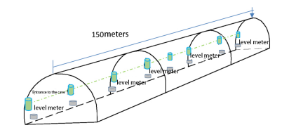
Case 2: Static level for monitoring tunnel bottom settlement and deformation [Summary description] Within a range of 150 meters from the left and right tunnel entrances to the tunnel, static levels are evenly distributed at 10m intervals on the tunnel bottom and tunnel side lining walls to monitor tunnel settlement and vertical deformation. As shown below: Tunnel settlement and longitudinal deformation monitoring system diagram 1. System composition The longitudinal deformation monitoring of the tunnel entrance consists of a static level, a data acquisition instrument/photoelectric transmission unit and other parts, as shown in the figure below. 2. System technical requirements a) System monitoring indicators b) Measuring range: 0~1000mm c) Measurement accuracy: 0.2mm d) Display resolution: 0.01mm e) Working temperature range: -30~+70°C f) Output voltage: DC12V~36V g) RS485 digital output h) Protection level: IP67 |
Case 2: Static level for monitoring tunnel bottom settlement and deformation [Summary description] Within a range of 150 meters from the left and right tunnel entrances to the tunnel, static levels are evenly distributed at 10m intervals on the tunnel bottom and tunnel side lining walls to monitor tunnel settlement and vertical deformation. As shown below: Tunnel settlement and longitudinal deformation monitoring system diagram 1. System composition The longitudinal deformation monitoring of the tunnel entrance consists of a static level, a data acquisition instrument/photoelectric transmission unit and other parts, as shown in the figure below. 2. System technical requirements a) System monitoring indicators b) Measuring range: 0~1000mm c) Measurement accuracy: 0.2mm d) Display resolution: 0.01mm e) Working temperature range: -30~+70°C f) Output voltage: DC12V~36V g) RS485 digital output h) Protection level: IP67 |
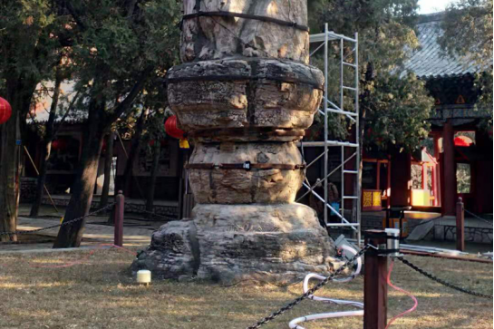
Case 3: Safe tilt settlement and automated monitoring plan for ancient building protection 1. Overview 1.1Project status According to my country's existing conventions in the maintenance and management technology of ancient buildings, daily inspections and regular inspections are adopted for management and maintenance. Routine inspections are mainly based on manual visual inspection, which makes it difficult to measure the structural parameters of the building; regular inspections cannot collect data continuously due to limitations such as long cycles, poor effectiveness, and insufficient timeliness, and can only provide time and space for local structural conditions. information and cannot provide an overall comprehensive status assessment. Therefore, in view of the key factors of safety hazards in ancient buildings due to their age, in order to prevent sudden structural damage and cumulative damage from endangering the safety of ancient building operations, in addition to establishing a complete daily management and maintenance system, it is also necessary to establish a long-term online A real-time safety monitoring system can collect comprehensive information reflecting the safety and health status of ancient building structures, assess the degree of structural damage and safety conditions in real time, and provide early warning before danger occurs, allowing managers to grasp the structure's operations in real time. conditions and make management decisions as soon as possible to ensure the normal operation and safety of ancient buildings. 1.2 Monitoring purpose 1.2.1 The ancient buildings are very old, and the impact of structural settlement is monitored and early-warned. Ancient buildings are old and their structures may change. Based on the long-term on-site survey results of ancient buildings, we can rationally select key equipment parameters, conduct real-time safety monitoring of its structural operating status, real-time assessment of its structural safety status, and conduct real-time identification and analysis of its service life. Early warning, and early warning for sudden and cumulative damage; long-term monitoring of its development and change trends can promptly assess the technical status of key structures, allowing managers to grasp the operating status of the structure in real time and make management decisions as soon as possible to avoid accidents occur. 1.2.2 Modern management and monitoring system Through in-depth research on the daily management and maintenance of ancient buildings, this system starts from building digital archives, developing digital full-platform inspection systems, digital inspection reports and safety assessment reports, and digital maintenance to unify dynamic monitoring data and manual maintenance data. Management, unified storage, and unified analysis and integration of data obtained from the two monitoring methods are a necessary complement and improvement to the automated sensing test and signal analysis remote control system. 1.3 Automated monitoring equipment The system collects data through front-end hardware, transmits it from the front-end to the monitoring server with the help of wireless data transmission, and realizes data sharing and storage of the entire network through the server. Users can conveniently monitor in real time through the network, mobile phones and other terminal devices, thereby realizing the connection of things. safety monitoring system. The main monitoring object of ancient building structures is settlement. Parameter indicators need to collect on-site physical quantities through corresponding sensors and demodulators, and transmit the data to the remote monitoring center database through Ethernet or wireless networks. Through the structural safety of the host computer, Monitoring system software performs data processing, analysis and risk assessment control.
1.4 System scheme design basis a.<<Building Construction Safety Inspection Standard>>(JGJ59-2011 J1334-2011) b.<<Basic specifications for railway bridge and culvert design>> (TB 10002-2005) c.<<Technical requirements for dynamic environmental monitoring equipment (FSU)>> (Q/ZTT 1008-2014) d.<<Regulations on Safety Production Management of Construction Projects>>(2008)111 2. Delivery cycle and time arrangement According to the influence of the weather and environment, reasonable working time arrangements require a minimum of 4-6 days of working time per week, and each working time is from 8:00 to 17:30 the next day, that is, the actual working time per day is 8 hours. Based on the actual working time and on the premise of ensuring safe construction, a large amount of equipment and labor will be invested to ensure that the construction cycle is completed on time. a) Automation equipment is ready for shipment: it takes about 3 days b) The automation equipment was installed and tested successfully, and the planned construction period takes 4 days. It will take 5 days to complete all automated monitoring installation and testing (single point). 3. Equipment and instrument parameters 3.1 Collection instrument
Central Collection System Technical Specifications
3.2 Settling equipment
Static level technical specifications:
3.3 Tilt equipment
T7000-H tilt sensor technical specifications:
4. Equipment parameters and installation 4.1 Equipment details
4.2 construction tools
4.3 Construction organization 4.3.1 Automatic monitoring system based on static level The system mainly consists of a liquid storage tank, base points, measuring points, and collection equipment. The static level includes a main container, a connecting pipe, a sensor, and other components. The static level uses the principle of connected liquid to observe settlement. The liquid storage levels connected by multiple universal connecting pipes are always on the same level. By measuring the liquid level heights of different liquid storage tanks, each static level can be calculated through calculation. Relative differential settlement of force level.
4.3.2 Settlement calculation method: Measuring point: current measurement value - initial measurement value = settlement change value Base point: initial measurement value - current measurement value = base point change value Calculation of settlement change: (Settlement change value – base point change value) X-1 = final settlement value
On-site construction drawings
Basic installation 7. Quality assurance and safety assurance measures 7.1 Add security protection Establish and improve the quality assurance system for safety monitoring projects, and formulate progress arrangements for each link of hole making, instrument and equipment procurement, burial installation, maintenance, observation and data collection based on the design documents approved by the supervision, and specify the quality assurance of each sub-item The person in charge regularly conducts safety production education for all employees and strengthens quality awareness to ensure that qualified safety monitoring projects and continuous and reliable observation data are provided to owners. 7.2 Precautions In addition to strictly complying with the relevant quality control provisions, special attention is also paid to: a. The instruments and equipment used for inspection have been certified by the national standard unit of measurement and their parameters are within the valid period of use. b. Secondary direct-reading instruments used for observation must be inspected (calibrated) once a month and meet the requirements stipulated in relevant technical specifications or factory instructions. Before replacing the instrument, check whether it is interchangeable. c. All information provided to the supervisor, including drawings, reports, manuals and data, etc., shall be clear and legible copies and blueprints, or printouts, or disk files, in a format approved by the supervisor, and with a systematic and continuous index. serial number. | |||||||||||||||||||||||||||||||||||||||||||||||||||||||||||||||||||||||||||||||||||
Case 4: Inclination sensor is used for debris flow and dam landslide monitoring and early warning 1 Overview Collapses, landslides, and debris flows are the main types of geological disasters. The degree of harm is second only to earthquakes. They erupt frequently. They are widely distributed and the degree of harm is extremely serious. According to incomplete statistics, from the founding of the People's Republic of China to the end of 2010, a large number of geological disasters occurred nationwide. There were more than 3,000 large-scale collapses, more than 2,000 landslides, and more than 2,000 debris flows, and there were hundreds of thousands of small and medium-sized collapses, landslides, and debris flows. Tens of thousands of villages, more than 100 large factories, 55 large mines, and more than 3,000 kilometers of railway lines in more than 350 counties across the country are seriously affected by collapses, landslides, and mudslides. Since the mid-1990s, it has caused more than 1,000 deaths every year and caused economic losses of more than 20 billion yuan. These data show that it is urgent to effectively reduce losses from geological disasters. Our inclination sensors are applied to landslide monitoring, transmitting the mountain status to the terminal in real time through wireless transmission, sending out early warning signals before landslides and collapses, and relocating people and important personnel. property, effectively reducing casualties and property losses. There are more than 8,000 ore bodies in the country alone, and their market prospects are broad. 2. Landslide and debris flow monitoring components a) We designed the following pile. The lowest end is a liquid level sensor, and 3 inclination sensors are distributed upward. A control system is installed inside and connected to the control system through the RS485 bus; it mainly relies on the functions of two sensors: liquid level sensor and tilt sensor. In areas prone to danger on the mountain, multiple holes should be set up vertically along the direction of the mountain, as shown in the figure below:
b) Each hole will deploy a liquid level sensor at the bottom and several inclination sensors at different depths. Since landslides in this area are mainly caused by rain erosion, the depth of the groundwater table is the first indicator of landslide risk. This data is collected by a liquid level sensor deployed at the bottom of the hole and sent by a wireless network. Inclination sensors can be used to monitor the movement of mountains. Mountains are often composed of multiple layers of soil or rock. Different layers move at different speeds due to different physical compositions and degrees of erosion. When this happens, tilt sensors deployed at different depths will return different tilt data, as shown in the figure below. After the wireless network obtains the data from each tilt sensor, through data fusion processing, professionals can judge the trend and intensity of the landslide and determine its threat. Landslides can be seen everywhere in disaster areas after earthquakes, especially landslides on both sides of traffic arteries, which pose a huge threat to rescue progress. 3. Landslide and debris flow monitoring components a) It can monitor mountain dynamics, including possible landslide areas, landslide scope, direction, predicted disaster occurrence time, etc. b) Centralized control system, all sensors are a node, and the Internet of Things network is fully monitored. c) The inclination sensor independently developed by our company has good reliability, full temperature compensation, dynamic compensation, etc., and is suitable for outdoor environments. d) Easy and convenient installation, no wiring required, solar power supply, wireless transmission. e) The address coding and terminal computer are equipped with a host computer control system, which can locate coordinates and comprehensively analyze data. f) Able to send out early warning signals before landslides occur and effectively move property to reduce losses.
| |||||||||||||||||||||||||||||||||||||||||||||||||||||||||||||||||||||||||||||||||||