 Solar power generation is divided into two types: solar photovoltaic power generation and solar photothermal power generation. At present, the development of solar photovoltaic power generation is faster and faster, making it a rapidly developing field. Currently, countries such as China, the United States, Europe, Japan, India, and Australia are developing rapidly. Mai Xinmin Micro has developed over ten different models of tilt sensors for photovoltaic tracking systems to meet customers from different countries.


Copyright © Breeze Co.,Ltd Introduction All rights reserved. Site Map
- +86571-56076080
- sales@memsmag.com
- Room B3250, 3rd Floor, Building 1 (North), No. 368 Liuhe Road, Puyan Street, Binjiang District, Hangzhou

Maixinminwei Industrial grade inclinometer / Tiltmeter sensor
Product application scenarios and solutions
A. Energy and Electricity The intelligent online monitoring system for tower tilt can effectively monitor the tower during operation of high-voltage transmission lines 24/7 online and in real-time. |
Case1:Tilt switch charging pile anti tilt safety monitoring
The working principle of the tilt switch 'anti tipping':When the host tilts or falls, the ball inside the tilt switch undergoes displacement under its gravity. Due to the detachment of the ball, the tablet returns to its original position, and the switch instantly disconnects and stops working. When the host is lifted, the ball returns to its original position and the host continues to operate normally. Charging Station Dumping Power Failure: When the charging station is connected to the vehicle and powered on, it should be ensured to tilt the charging station in any direction, and all charging stations cannot be powered off. The charging station should have the function of tipping, stopping, and powering off to avoid accidental collision accidents that may cause secondary electric shock injuries to personnel.
T70-C is a high-performance 1-channel switch output model launched by Mai Xinmin Micro, which measures the tilt angle in any direction of the horizontal 360 ° vertical attitude. When the tilt angle value is greater than the preset tilt threshold, it will output a switch signal to drive the solenoid valve. The alarm threshold is calibrated at the factory, with built-in relays and voltage signals (output voltage=supply voltage). Users can also set the alarm angle threshold themselves.
|
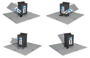
Case 2: Inclination sensor for solar photovoltaic power generation tracking system
Composition of solar photovoltaic tracking system: 1. Solar photovoltaic tracking systems generally consist of inclination sensors, motors, worm gears, and controllers. Solar photovoltaic tracking systems are divided into three types based on specific applications: horizontal single axis photovoltaic tracking systems, oblique single axis photovoltaic tracking systems, and dual axis photovoltaic tracking systems. Not only can it comprehensively increase the power generation of the power station, but it can also adapt to various complex terrains and application scenarios according to local conditions. 2. The solar photovoltaic tracking system needs to adjust the tilt angle of the solar photovoltaic panel, so that the solar photovoltaic panel can make timely adjustments according to the movement of the sun, in order to achieve the maximum solar radiation by always allowing the sunlight to shine vertically on the solar photovoltaic panel. Although the angle of the sun varies widely throughout the day, the angle of sunlight remains almost constant for a certain period of time. The system can calculate the direction and angle information of the local sun for each day of the year based on the local longitude and latitude, and store the information in the controller software. This allows the angle information of the photovoltaic panel measured by the tilt sensor to be compared with the angle information of the sun stored by the controller, and then controls the motor to adjust the optimal position of the photovoltaic panel at that time. 4. The inclination sensor, as the eye for real-time measurement in solar photovoltaic tracking systems, is one of the key equipment for optimizing solar energy reception rate. There are certain requirements for the accuracy of tilt angle sensors, and the tilt angle sensor independently developed by Mai Xinmin Micro is currently a mature application and multiple solar photovoltaic projects in the market. Maixinminwei recommended tilt sensor model for single axis photovoltaic tracking systems and oblique single axis photovoltaic tracking systems is T7-B. Its maximum measurement angle range is 360 °, with RS485 output. It adopts industrial devices with stable performance and high reliability, and has protection functions against touch and misconnection. It is wind and sand resistant, salt spray resistant, and UV resistant, fully considering the complex application scenarios of solar photovoltaic. Maixinminwei recommended tilt angle sensor model for the dual axis photovoltaic tracking system by Mai Xinmin Micro is T70-A (RS485), with a dual axis structure and horizontal installation. It measures the tilt angle in the X and Y axis directions, with a measurement range of ± 90 degrees, and simulates voltage output. All products are made of industrial devices with stable performance and high reliability, and have protection functions against touch and wrong connection. |
Case 3: Tilt angle sensor for power tower and communication tower tilt safety monitoring
1. System design philosophy The intelligent monitoring system for the tilt of transmission line towers consists of a front-end monitoring device and a back-end monitoring center. The front-end monitoring device is designed using high-precision dual axis inclination sensors and microelectronic control technology. The dual axis tilt sensor can measure the tilt angle of the tower in real-time along and across the line direction. The microprocessor sets its working mode and transmission method through program instructions, including zero point setting, transmission baud rate setting, and data encoding method. The tilt data monitored by the dual axis tilt sensor adopts a transparent transmission method, communicates with the microprocessor through RS232 serial port, and transmits the measured data to the non volatile data storage area of the microprocessor. The microprocessor processes the measured values through software. Analyze and calculate, and then compare with the set threshold. If the limit is exceeded, the microprocessor will initiate a review, measurement, and confirmation process for the dual axis tilt sensor to prevent misoperation. After confirming that the measurement results have indeed exceeded the limit, the microprocessor sends information such as the line tower number, tower tilt angle and direction, and device power voltage to the monitoring center and relevant staff's mobile phones in a short message (currently only supported in Chinese) mode through the GSM short message module, reminding staff to pay attention to and check the operation status of the tower in a timely manner. In daily operation, the backend monitoring center can set the parameters of the monitoring device through SMS commands as needed, such as setting the monitoring time interval, zero adjustment, threshold crossing, and reporting time for the dual axis angle sensor. 2. Characteristics and Functions of System Software and Hardware 2.1 ATmega128 microprocessor: The ATmega128 microprocessor is used, and its functional characteristics are as follows. 1) Adopting a 232 bus structure, the internal data bus and instruction bus of the chip are separated, and different widths are adopted to accelerate the execution speed of instructions. 2) Adopting a streamlined instruction set has improved the compression rate of the code. 3) Very strong anti-interference ability, suitable for stable operation in complex electromagnetic environments and independent power supply situations. 2.2 Solar photovoltaic power supply system The power supply system consists of monocrystalline silicon solar cells, solar controllers, and lithium batteries. It is based on the float charging and lithium battery supply methods of monocrystalline silicon solar cells. The main parameters of solar panels are no-load open circuit voltage of 7.5v and short circuit current of 240MA, which are used to control the working status of the entire system and provide overcharging and discharging protection for lithium batteries. The device battery adopts a lithium battery pack, which makes the entire power supply system small in size and ensures reliable operation of the device in the absence of sunlight
2.4 Dual axis inclination sensor High precision dual axis inclination sensor has the characteristics of small volume, waterproof, dustproof, easy installation, low working voltage, small temperature drift, and wide measurement range.
1) Monitoring device parameter settings: Set the monitoring time interval for the dual axis tilt sensor, zero point adjustment for the tilt sensor, and device threshold parameters through SMS. 2) Display: It can be displayed according to pre-set line classification, tower number classification, and historical value curve. 3) Storage content: real-time data, historical data, operation records, and current status. 4) Historical data organization: Organize historical data files, delete selected historical data files, and delete previous historical data. 3 Main technical challenges to be solved 3.1 Power saving mode design: The power supply of the monitoring device is based on the floating charging of monocrystalline silicon solar cells and the supply point of lithium batteries. To ensure long-term stable and reliable operation of the device, low-power design has been carried out in terms of power supply and device operation. 1) The GSM short message module operates in an alarm state for a long time, and is only activated when reporting or exceeding the limit every day. The module consumes a constant current during normal times. 2) The atmega128 adopts a timed sleep and start mode, with a static working current of less than 0.1MA 3) The inclination sensor is designed as a timed (every n minutes or adjustable) measurement on mode, which is immediately turned off after measurement to reduce current consumption. Through the above measures, the current consumption of the monitoring device is constant during static operation, and the working current during inclination measurement is constant. The average working current of the entire device is very small. 3.2 Anti interference design: The monitoring device operates on the line tower for a long time, and electromagnetic interference is relatively serious. Therefore, reliable anti-interference measures must be taken. The specific design measure is to use shielded wire protection for the inclination sensor; The control core, namely the ATMega128 low-power microcontroller with embedded control technology, has strong anti-interference performance. At the same time, the software adopts sleep and self recovery design to further enhance the stability and reliability of the monitoring device, ensuring long-term reliable operation. The intelligent monitoring system for tower tilt of transmission lines has high measurement accuracy, low power consumption, strong anti-interference ability, simple installation, and maintenance free. The design fully considers the operating environment of the device and the requirements for reliable and stable operation. At the same time, adopting a monitoring center and monitoring terminal point-to-point mode facilitates centralized management. Through on-site operation on 220 kV transmission towers, it has been found that the operation is stable and reliable, and can also be widely used. The product is used for horizontal status monitoring of communication towers, buildings, bridges and other equipment, and has good application performance and market prospects. |
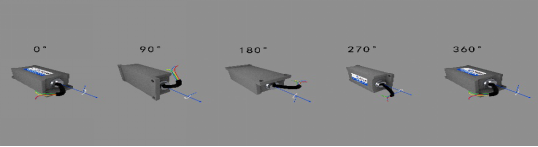
Case 4: Wind turbine tower oscillation attitude monitoring
1.1. Overview of Architecture Design This plan aims to achieve real-time monitoring of wind turbine tower oscillation, cabin heading, and other data by deploying attitude sensors on each layer of the wind turbine and RTK monitoring terminals in the wind turbine cabin, in order to restore the real-time attitude of the wind turbine tower. 1.2 Description of each part of the architecture The architecture design of this project includes the following parts: 1) Device Management Cloud Platform: refers to the cloud platform system used to uniformly manage the status of various wind turbines and their supporting facilities. It is also a centralized cloud platform for the storage, supervision, and analysis of data collected by various sensors in this project. 2) Edge computing terminal: refers to the computing platform used for data pre-processing of on-site acquisition, which can integrate and pre-process the data of multiple local systems, improve the monitoring efficiency, improve the real-time performance of the system, and reduce the pressure of cloud platform on data access management, storage management, etc. 3) Attitude sensors: acceleration and inclination sensors, deployed on various maintenance platforms of the wind turbine tower. By monitoring the three-dimensional acceleration, angle, and other data of the wind turbine tower, the attitude monitoring of the wind turbine tower is achieved. Figure 2 Installation and Construction Drawing of Fan Swing Angle and Acceleration 4) Self differential RTK terminal: Two antennas are fixed 1 meter apart and installed outside the fan compartment, providing high-precision real-time longitude and latitude position information. 5) RTK reference station: An RTK reference station is set up in the wind farm booster station, and differential communication between the reference station and each wind turbine RTK terminal is achieved through the existing wind turbine ring network, with an interface method of RJ45 (Ethernet). 2. Hardware requirements à 2.1. Self differential RTK terminal à positioning accuracy n Static ≤ 1cm n Dynamic ≤ 2-3cm à Sampling frequency: 10Hz (not less than 5Hz) à Function: positioning+orientation à Communication interface and protocol n Directional positioning data transmission: 485 bus ModBus protocol n Differential data: Ethernet communication à 2.2. Attitude sensor à Output data: 3D acceleration and angle; à Angle range: X, Z axis ± 180 °, Y axis ± 90 ° à Angle accuracy X. Y-axis static: 0.05 ° Dynamic state of X and Y axes: 0.1 ° Z axis: 1 ° à Sampling rate: ≥ 100Hz à Speed range: ± 5g à Communication method: 485 bus ModBus protocol à Strong magnetic field environment: need to resist magnetic field interference |
Case 5: Remote transmission tower inclination measurement online monitoring system solution 1. Necessity of the project The transmission lines are basically overhead lines. Since the lines are erected in the air, they need to bear the effects of mechanical forces such as dead weight, wind, rainstorm, ice and snow, and the erosion of harmful gases such as wind and sand. The operating conditions are very bad. When the transmission line passes through unfavorable geological areas such as desert areas, high salt soil areas, goaf areas, and mountainous landslide areas, under the influence of natural environment and external conditions, the foundation of the tower is prone to sliding, tilting, cracking, and other phenomena, leading to tower deformation, tilting, and even tower breakage. The inclination of the tower causes an unbalanced force on the grounding wire of the tower, resulting in changes in the force on the tower, insufficient electrical safety distance, and affecting the normal operation of the line. Tower collapse and disconnection will paralyze the power supply line, seriously affecting people's production and life, and causing huge losses. In the early stages of the development of tower tilt phenomenon, it was difficult for line patrol personnel to observe small changes with the naked eye. At present, there is an urgent need to use intelligent data monitoring devices for online monitoring and fault analysis diagnosis of the tilt of transmission line towers, in order to detect hidden dangers, eliminate them in a timely manner, and improve the reliability of transmission line operation. Tower tilt monitoring can monitor the tilt of the tower in real-time, and timely understand the safety and reliability of the operating tower. Based on the development trend of tilt monitoring data, various ways of timely warning and guidance for excessive tower tilt conditions are provided to guide maintenance and repair, remind operation and maintenance personnel to reinforce the foundation and prevent tower collapse accidents. The online monitoring system for tower tilt can effectively monitor the tower during operation of high-voltage transmission lines 24/7 online and in real-time. It mainly includes two parts: a tower tilt monitoring device and a background comprehensive analysis software. The system measures and reports various state variables of the tower tilt transmission line, and transmits the data to the background comprehensive analysis software system for analysis and decision-making through communication methods such as 3G/4G/GPRS/CDMA. This accurately reflects the current various states of the transmission line, enabling power system operation and management personnel to grasp the actual situation of the line operation, Helping them make decisions and conduct safety assessments is of great significance in preventing power grid accidents. 2. Main content 2.1 Monitoring methods and content 2.1.1 Monitoring method: By installing dual axis angle sensors and tower tilt devices on the tower, real-time online monitoring, early warning, and analysis decision-making of the operation status of the line tower can be achieved. 2.1.2 Monitoring content: Real time monitoring of bidirectional tilt angle (along and perpendicular to the line direction) and micro meteorological conditions (temperature and humidity, wind speed and direction, etc.). 2.2 Installation location of monitoring devices 2.2.1 Installation principles 1) According to the General Technical Conditions for Online Monitoring System of Overhead Transmission Lines (Q/GDW 245-2008). 2) The selected installation location and appearance structure of the device should not affect normal transmission line maintenance and repair work. 3) The installation of the device should be neat and firm, with necessary protective measures and rust prevention treatment. 4) Sensors and data concentrator devices are connected with dedicated cables to avoid electromagnetic interference. 5) The installation point on the tower facilitates the fixation of the monitoring unit and overall angle adjustment. 6) During installation, use standard angle measuring tools to pre adjust the installation angle of the device. 7) For lightning protection, waterproofing, and convenient installation and maintenance, the cable of the inclination sensor should be threaded into the cable duct. 8) The sensor is within the effective protection range of lightning protection facilities. 9) The casing of the device is grounded through a tower. 2.2.2 Installation position 1) The installation position is generally selected at the tower position in the coal mine goaf and settlement area; Adverse geological sections, such as muddy areas, mountainous areas prone to landslides and weathered rocks, or hills. 2) The tower tilt monitoring device is installed on the cross arm of the tower, and the cable ducts are routed along the tower components at fixed intervals of 0.5m; Cables cannot be erected overhead. 3. Technical Proposal 3.1 System Structure Schematic Diagram: The entire system consists of a tower tilt monitor and a background comprehensive analysis software system. The system structure diagram is shown in the following figure: Figure 1: Structural diagram of online monitoring system for tower tilt 1) Tower tilt monitor: The tower tilt monitor is installed on the cross arm of the tower, and has a remote wireless communication interface for data communication with the comprehensive analysis software system. The monitor can self check, collect, measure, and transmit the measurement results to the comprehensive analysis software system. 2) Background analysis software system: The comprehensive analysis software system consists of a data communication module, a data processing server, a client, an uninterruptible power supply, and a comprehensive analysis software. The comprehensive analysis software can uniformly receive data from the tower tilt monitoring instrument, display, analyze, and manage it, query and statistics historical data, generate reports, and make decision support analysis. The system can interface with other MIS systems and share data. 3.2 Monitoring System Composition and Operating Environment à 3.2.1 Monitoring device Hardware composition n Dual axis angle monitoring sensor: one set n Data conversion module: one set n Power system: solar panels, charging controllers, batteries n Sub station communication system: GSM wireless data transmission module and mobile phone card n Main chassis n Installation and fixing fixtures for front-end equipment Operating environment n Environmental temperature: -25 ° C~+45 ° C n Operating temperature: -40 ° C~+85 ° C n Relative humidity: 5% RH~100% RH n Atmospheric pressure: 550hPa~1060hPa à 3.2.2 System software à Hardware configuration: server (host can store monitoring data for more than 10 years), data communication module, client, uninterrupted power supply à Software configuration n Server operating system Windows Server 2000 n Database Management System SQL Server 2000 n Client operating system Windows XP/Windows 2005, etc., IE browser n Comprehensive analysis software à 3.3 Main technical parameters à Scope of use n Online Status Monitoring of Operating Poles and Towers in 66kV~500kV Transmission Lines n Online Status Monitoring of Operating Poles and Towers in 66kV~500kV Substation sworking voltage:DC12V à Power supply method: solar energy+battery à Communication method: 3G/4G/GSM/CDMA/GPRS à Data channel: RS485/TCP/UDP transmission à Working power consumption: ≤ 1W; Standby power consumption ≤ 0.1W à Tilt detection unit n Line direction angle range: -90 °~+90 °; Measurement accuracy: ± 0.01 ° n Vertical angle range of the line: -90 °~+90 °; Measurement accuracy: ± 0.01 °; à Temperature measurement range: -40 ℃~+95 ℃, measurement accuracy: 0.5 ℃ à Humidity measurement range: 0-100% RH, measurement accuracy: 2% RH à Wind speed measurement range: 0-75m/s, accuracy: ± (0.5+0.03 V) m/s à Wind direction measurement range: 0-360 °, accuracy: ± 5 ° à work environment n Humidity: not greater than 98% RH n Protection level: IP65 à Software system: lifetime free upgrade; 3.4 Monitoring System Features à Anti interference: anti electromagnetic, waterproof, lightning protection, ensuring stable and reliable system operation à High measurement accuracy: high-precision, high-resolution, and highly reliable digital tilt sensors à With data collection, measurement, and communication functions, the measurement results are transmitted to the backend comprehensive analysis software system through a communication network à Power on self start function à With online self-diagnosis function à Time synchronization function, capable of receiving time synchronization commands from the comprehensive analysis software system, once a day, with an error of no more than 5s à The device is designed with small size, convenient installation, and can be installed with electricity without maintenance. After installation, it will not cause safety hazards to the structural characteristics of the line itself and subsequent operation and maintenance à Having appropriate interfaces for local debugging à Data temporary storage function, which can store data for more than 3 days in case of communication abnormalities à The device host adopts solar energy+battery power supply mode, and the tower tilt angle acquisition unit adopts solar energy+lithium battery power supply mode. Under continuous rainy and rainy conditions, the device host can operate normally for at least 30 days, and the tower tilt angle acquisition unit can operate normally for at least 1 year à In areas with frequent typhoons in coastal areas, wind speed sensors can be installed. Using wind speed as a parameter, draw a curve of wind speed over time and display it in the same coordinate system as the curve of inclination over time. It can be clearly seen that the wind speed has an impact on the inclination angle. 3.4.2 Characteristics of comprehensive analysis software system à Capable of automatically receiving data from data collection units at a fixed time à It has the function of remotely setting the collection method (automatic or controlled) and automatic collection time à The backend software can set the data collection density according to user needs à Can send timing commands to data acquisition units à Can remotely modify the IP address and port number of the data collection unit à Ability to query and analyze historical data, and automatically generate reports à Equipped with alarm prompt function à Can interface from other MIS systems à Lifetime free upgrade available à Statistics, analysis, and output of monitored data, displaying relevant parameters in the form of digital lists, curves, and charts; And based on its historical and current data, a trend chart can be drawn to infer the development speed and trend of tower tilt, and determine the law of periodic changes in tower tilt à On the trend chart, the corresponding date, time, and characteristic parameter values of any point can be quickly read out, which can reflect the change process of characteristic values and predict the occurrence of early tower tilt faults 3.5 Communication, power supply, and operation mode of monitoring system 3.5.1 Communication method: The tower tilt monitor adopts 3G/4G/GPRS/CDMA communication method to transmit data 3.5.2 Power supply method: The tower tilt monitor is powered by solar energy, and the power supply includes solar cell components, batteries, and charge discharge controllers. The power supply time of the battery without sunlight is more than 30 days, and the service life of the battery is more than 5 years. 3.5.3 Operation mode à The tower tilt angle acquisition and monitoring terminal has two working modes, automatic acquisition and controlled acquisition. The automatic collection method is to collect on-site data according to the preset alarm working mode, and then automatically upload the collected data to the backend server. The client can connect to the server to download monitoring data à Controlled collection method is a remote data collection terminal that waits for the client to send a command to collect monitoring data or other control commands. Only after receiving the control command, it will take corresponding actions. This mode can be used for customers to instantly obtain on-site monitoring data and set the working status in real time. 4. Project significance The online monitoring system for tower tilt is a cutting-edge technology. After the implementation of the project, it can technically ensure the safe operation of the power grid and greatly improve the level of line operation management, opening up a new approach for line inspection and condition based maintenance, which has enormous economic and social benefits. With the development of intelligent power grids and the vigorous promotion in the industry, the online monitoring system for transmission lines is in the stage of gradual development and heating up, and it is believed that it will soon reach the leading technical level in China. 4.1 Direct economic benefits After the online monitoring system for tower tilt is put into operation, considerable economic and social benefits can be achieved. Due to improving the reliability of equipment operation, achieving fewer power outages and more power supply, facilitating condition based maintenance and reducing repetitive power outages caused by annual planned pre test minor repairs; Transmission line monitoring can be carried out without power outage. In general, each transmission line can provide an additional power supply of about tens of millions of kilowatt hours per year, saving travel and shift costs of several hundred thousand yuan. If fully promoted and used, the benefits are difficult to estimate. 4.2 Indirect Economic Benefits 4.2.1 Improving power supply reliability: By using online monitoring of tower tilt, it is possible to detect small changes in tower tilt that are difficult to observe with the naked eye, helping the operating department to detect hidden dangers and eliminate faults in a timely manner, thereby improving the reliability of transmission line operation. 4.2.2 Improving personal and equipment safety: The implementation of online monitoring technology for transmission lines has reduced the workload of power outages and live maintenance, and reduced the probability of personal accidents. The original inspection required personnel to regularly visit the transmission lines, and the transmission lines were located in areas with poor geological conditions. In addition, in harsh weather conditions, workers were very tired, and in actual work, the risk of personal accidents occurred frequently within the system. The use of online monitoring technology for transmission lines reduces the need for personnel to conduct regular inspections, which is very beneficial for ensuring personal and equipment safety. |
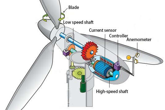
Case 6: Application of inclination sensor and acceleration sensor in offshore wind power generation equipment The current energy issue has increasingly become a top priority that constrains the social development of various countries. Therefore, governments around the world are constantly trying to find new energy and develop renewable energy. Among them, wind power generation, especially offshore wind power generation, has become a hot topic for new energy investment and construction. In the construction of wind power generation equipment, there are many applications of safety monitoring technologies such as acceleration sensors, current sensors, and inclination sensors.
1. Acceleration sensor Among various facilities used for wind power generation, wind turbines are crucial power generation equipment for converting wind energy into electrical energy. Simply put, the principle is that wind energy is converted into electrical energy through the impeller, spindle, gearbox, and generator. Among these components, wind turbine blades are highly susceptible to flutter under wind loads, which can lead to structural damage in severe cases. In addition, wind turbines may experience significant vibrations in the cabin in various directions due to various reasons during operation, which can pose a threat to the normal operation of the wind turbine. At this point, it is necessary to use acceleration sensors to monitor the vibration of components such as the gearbox, spindle, and motor stator of the wind turbine. 2. Tilt sensor Mainly used for angle measurement work to monitor the level of wind turbines. When constructing offshore wind power towers, in order to avoid potential tilting of wind turbines at high altitudes, which threatens the normal operation and safety of the towers, it is necessary to use tilt sensors to monitor the verticality of the wind turbines for a long time. Once the tilting exceeds the safety value, timely warning can be given, and personnel can be notified to inspect and maintain, in order to ensure the stability of daily power generation work. 3. Limit switches and current sensors In the process of wind power generation, due to the constantly changing size of the wind force, it is necessary to adjust the wind propeller of the generator to maintain a constant speed and ensure the stability of the power generation process. At this point, a limit switch device can be used to install it at both ends of the limited range of wind blade angle change to protect the relevant circuit from triggering the pitch operation when the pitch reaches the limit position, and avoid damage to internal electronic devices caused by this.
In addition, complex and ever-changing wind farms can also make the voltage of power generation very unstable. In order to process the generated electrical energy and ensure the optimal operation of the generator, it is necessary to use current sensors to accurately measure the current magnitude of wind turbines. Generally speaking, current sensors are responsible for measuring the current on the DC and AC sides to ensure the stable and normal operation of the inverter. |
Case 7: Application of inclination sensor and static level for gate inclination settlement monitoring A certain company uses our company's tilt sensor and static level to observe the deformation of ship lock gates (mainly tilt and settlement observation). The system composition of the plan is as follows.
The automatic monitoring system for gate deformation mainly consists of a liquid storage tank, a connecting pipe, a static level, and a deformation monitoring background. The details are as follows: ① Liquid storage tank ② Reference point level ③ Monitoring point level ④ Wireless gateway ⑤ Solar panel ⑥ Liquid tube (red) ⑦ Ventilation tube (yellow) ⑧ Observation cable (black) During the deformation observation process, a static level is uniformly arranged on the approximate contour line according to the direction of the gate. Monitoring nodes are mainly arranged on the gate, and settlement observation is carried out jointly by the storage tank, reference point, and testing point. This can achieve functions such as storage, preprocessing, management analysis, visual analysis, and limit warning of settlement monitoring data. 2. Scheme design According to the specific situation of the company's ship lock, a total of 4 high-precision settlement monitoring gates (8 gates) need to be installed. According to the requirement of monitoring key parts at the head and tail of the gate, a plan is proposed: each gate forms an independent monitoring unit, which includes 1 liquid storage tank (blue rectangle), 1 benchmark equipment (red triangle), and 2 monitoring equipment (red dot), A total of 8 independent monitoring units (green circles) form a deformation monitoring system. 3. Overall layout diagram (based on actual situation)
Schematic diagram of independent units
Install two static level gauges on the gate, and install a benchmark static level gauge near the house. |
Case 8: Application of Automatic Control System for Water Conservancy Valves
The inclination sensor is widely used in the automatic control system of water conservancy valves. At present, the front-end equipment of the flip plate water valve control system is generally composed of the flip plate water valve, oil cylinder, and a steel cable valve opening meter fixed on the oil cylinder. The oil cylinder is connected to the upper end of the valve through a rotating shaft, and the expansion and contraction of the oil cylinder drives the opening and closing of the valve. During the expansion and contraction process of the oil cylinder, the steel cable is driven to expand and contract, and there is a certain functional relationship between them. As long as the length of the steel cable is measured, the real-time angle of the gate can be calculated. However, due to the exposed external steel cables, they are easily corroded, causing instability in the opening meter. Therefore, in recent years, new non-contact control technologies have gradually been adopted, which use inclination sensors to measure the angle of the oil cylinder, which can effectively compensate for the shortcomings of the original system. |