


 Standard requirements for high-altitude hanging baskets:
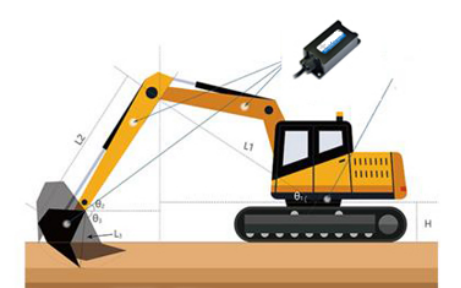
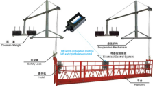 resolution is 0.01 degrees, the accuracy is 0.1 degrees, with temperature compensation, industrial grade, the output mode is relay output, you can choose normally open or normally closed, die-cast aluminum shell, protection grade IP67, easy to install It is very simple. It is installed on the bucket of the crane machine to determine the inclination angle of the hanging basket to avoid operational errors caused by the operator's lack of understanding of the high-altitude environment, such as the influence of high-altitude wind, the movement of high-altitude workers themselves, and the high-altitude distance. It is difficult to accurately judge the tilt and rollover accidents caused by various factors such as the distance.
Copyright © Breeze Co.,Ltd Introduction All rights reserved. Site Map
- +86571-56076080
- sales@memsmag.com
- Room B3250, 3rd Floor, Building 1 (North), No. 368 Liuhe Road, Puyan Street, Binjiang District, Hangzhou

MXMW
Industrial Grade Tilt/Inclination Sensor
Product Application Scenarios and Solutions
B. Construction machinery The inclination sensor can measure the absolute inclination angle of the tunnel excavation body, and can also calculate the deviation distance and other data through the inclination angle, which plays an irreplaceable role in correcting the guidance. Ensure that it digs along a prescribed trajectory. |
Case 1: T7000-I wireless tilt product is used to detect the vertical tilt offset of tower cranes
1. Hardware design requirements → Measuring range: ±15° → Signal output method: ZigBee wireless transmission (within 1.6km) → Accuracy 0.001°, resolution 0.0005° → Response frequency: 100HZ, 0.01 seconds → Power supply mode: Installed on the upper end of the tower crane, it is inconvenient to frequently disassemble and install the battery. It can be connected to an external power supply, with a built-in 6000mAH battery and an external solar panel. 2. Software design requirements → Corresponding modules can be added according to the number of tower cranes, and the modules can be named (such as: 1# tower crane, 2# tower crane, 3# tower crane...) → The height of the tower crane can be entered under each corresponding module (e.g.: tower crane height: 60m) → Assign a tolerance to all modules, that is, the verticality deviation limit of the tower crane: 4H/1000 (H is the height of the tower crane, in mm) → Generate a fluctuation line chart in the X and Y directions under each module. The sampling interval can be adjusted, and the red line of the limit value and the real-time X-axis and Y-axis verticality deviation values are displayed, as shown in the figure:
→ For each module, if the deviation value exceeds the limit, set a buzzer alarm to remind → Set up the report generation function, which includes the tower crane number, tower crane height, X-axis and Y-axis verticality deviation values (differentiating between positive and negative directions). The report file format is mainly an EXCEL table. |
Case 2: Inclination sensor application for safe operation of coal washing and mining machinery
Surface coal mining machine, as the name implies, is a coal mining machine for mining open pit mines. In order to ensure the working safety of the coal washer, the chassis of the entire equipment needs to be leveled before work to ensure construction safety. By installing a T7000-K dynamic inclination sensor to measure the inclination angle of the chassis in all directions, the angle output signal is sent to the PLC to drive the hydraulic cylinder to achieve the leveling of the chassis. The angle measurement of the machine arm is used to calculate the lifting height and prevent the entire equipment from tipping due to excessive lifting, causing property damage and casualties. Surface mining machines work in high temperature, high dust, and corrosive environments for a long time, and the sensors act as the senses of the mining machines. If there is a problem with the sensor, it will have a big impact on work efficiency and safety issues. T7000-K News Inclination sensor, suitable for water, oil, steam, |
Case 3:T7000-L Analysis of Accelerometers Used for Monitoring and Controlling Roller Rolling 1. The importance of monitoring the rolling quality of road rollers With the development of information technology, informatization and digitization have gradually penetrated the entire lifecycle of engineering construction and operation. In recent years, the rapid development of the Internet of Things and mobile technology has once again promoted the new application of high-precision measurement, positioning technology, and intelligent technology in construction process control. These innovative products provide scientific and effective means to control the quality of the construction process, improve work efficiency, and ensure construction safety.
2. T7000-L Accelerometers Sensor Used in the Quality Monitoring and Analysis System of Roller Compaction
|
Case 4:Shield Tunnel Boring Machine
The shield tunneling machine, also known as the shield tunneling machine, is a specialized engineering machinery for tunnel excavation. The basic working principle of the shield tunneling machine is a cylindrical steel component that advances along the axis of the tunnel and excavates the soil during the process. The shell of this cylindrical component is commonly known as a shield, which serves as a temporary support for the excavated yet unlined tunnel section. It not only bears the pressure of the surrounding soil layer, but also bears the groundwater pressure and keeps the groundwater out. Excavation, soil dumping, lining and other operations are generally carried out under the cover of the shield of the shield machine. Widely used in tunnel engineering such as subways, railways, highways, municipal facilities, and hydropower. However, in the process of shield tunneling machine operation, it is very difficult to ensure that it excavates along a designated trajectory. Its control system integrates optical, mechanical, electrical, hydraulic, sensing, and information technology, and has functions such as excavation and cutting soil, conveying soil debris, assembling tunnel lining, measuring and guiding deviation correction. It involves multiple disciplines and technologies such as geology, civil engineering, machinery, mechanics, hydraulic, electrical, control, and measurement, The inclination sensor is an important part of this control system. The inclination sensor can not only measure the absolute inclination angle of the shield tunneling machine body, but also calculate deviation distance and other data through the inclination angle, playing an irreplaceable role in correcting guidance. In addition, the control system composed of inclination sensors, other sensors, and motors makes the shield tunneling machine more automated, labor-saving, and faster in construction speed. |
Case 5:T7000-K Dynamic inclination sensor installation and posture control during rotary drilling rig construction With the continuous heating up of the domestic construction machinery industry, rotary drilling machines can be seen everywhere in some building and road construction sites, and are widely used in various foundation construction projects such as cast-in-place piles, continuous walls, and foundation reinforcement. The rotary drilling rig is a pile construction machinery used for on-site grouting pile drilling construction in pile foundation engineering. By configuring different drilling tools and adopting corresponding drilling techniques, the drilling rig can be suitable for various complex formation drilling operations. Rotary drilling rigs generally use hydraulic crawler type telescopic chassis, self lifting and foldable drilling mast, telescopic drilling rod, with automatic verticality detection and adjustment, digital display of hole depth, etc. The overall operation of the machine generally adopts hydraulic pilot control and load sensing, which can operate on large construction sites, improve work efficiency and project progress. Application of inclination sensor in monitoring rotary drilling rigs The center of gravity position of the rotary drilling rig is a key factor affecting its stability. There are many factors that affect the center of gravity position of the rotary drilling rig, including static factors such as the angle between the chassis and the horizontal plane, the position of the luffing mechanism, the inclination of the mast, and the weight of each component of the drilling rig; Dynamic factors include pressure, lifting force, rotational speed, etc. When drilling with a rotary drilling rig, it is necessary to erect and adjust the mast of the rotary drilling rig, that is, first move the rotary drilling rig to the position where the drilling operation is located, and the display of the rotary drilling rig displays the working screen of the mast. The deviation of the X-axis and Y-axis directions of the mast can be observed in real-time from the working screen of the mast. By measuring the inclination of the corresponding components on the rotary drilling rig, the variable amplitude boom, and the mast through inclination sensors, the center of gravity position of each component can be calculated. Combined with the weight of each component, the static center of gravity coordinates of the rotary drilling rig can be determined. Real time attitude angle control of rotary drilling rig using Mai Xinmin micro tilt sensor The T7000-K dynamic high-performance inclination sensor is installed at the drill pipe end, which can achieve real-time dual axis attitude measurement under the motion conditions of the drill pipe structure. The T7000-K high-precision static inclination sensor is installed on the vehicle chassis, which can accurately measure the attitude of the vehicle relative to the horizontal plane. The measured posture, combined with the three-dimensional mechanical model of the rotary drilling rig, can calculate the spatial coordinates of the vehicle's center of gravity relative to the horizontal coordinate system in real-time. When the actual center of gravity exceeds the pre calculated safe space area of the vehicle's center of gravity, the system will give a safety alarm, the motion mechanism will pause execution, and the center of gravity will be automatically or manually adjusted to the safe area to avoid dangerous accidents. |
Case 6:Measurement and control of the verticality of the mast of rotary drilling rigs and pile drivers using dual axis inclination sensors The verticality of the mast determines the qualification of the drilling hole, especially for pile drivers. Verticality is an important indicator of the reliability of buildings. Therefore, how to maintain good verticality or drill at a certain angle is a common problem encountered during the construction process. In an electro-hydraulic control system, this function can be achieved by directly installing a dual axis inclination sensor on the mast. At the same time, operators can input tilt data through the PLC's human-machine interface device, and the drilling rig will automatically drill according to the set angle. Select the T700-I dual axis digital inclination sensor to monitor the current angle value in real-time. This is a horizontal sensor for dual axis measurement, combined with the DD-100 inclination display instrument, which can visually see the vertical angle value on the screen. This solution is the most concise and cost-effective, and our company has provided this solution configuration to many enterprises. The instrument panel can be placed in the driver's cab and can be installed with holes or directly fixed in a convenient location. The sensor is installed on the mast and connected to the instrument through a dedicated connecting wire. Simply connect the instrument to a 24V DC power supply. There are 2 meters, 5 meters, 10 meters, 12 meters, 15 meters and other specifications available for connecting cables. Function description à Absolute angle display (default screen) à Display of relative angle (press the up and down arrows to switch screens) à Relative zero reset (6 9-digit keys set to zero) à Alarm angle setting (switch to the alarm angle setting interface to set the alarm angle value) |
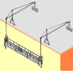
Case 7: Inclination sensor, hanging basket balance control safety detection
1. Requirements for overload detection (protection) devices → The hanging basket should be equipped with an overload detection device to avoid personal danger and mechanical damage caused by overloading. This device can detect the load of personnel, equipment and materials on the platform → Overload detection device should be installed on each hoist → Overloading when the platform is rising, falling or stationary should be detectable during use. → The platform overload device should be triggered on or before reaching 1.25 times the ultimate working load of the hoist. → Once the overloading device is activated, it will stop all movements except descending until the overloading load is removed. → When the overload device is triggered, the overload indicator will continuously send out a visual or audible signal to alert the operator on the platform → Preset components of the overload device must be protected against unauthorized adjustment → The design of the overload device should enable it to carry out the static load and dynamic load tests required by this standard. The overload device should work within the range of 1.6 times the ultimate working load of the hoist. The overload device should be able to withstand a static load of three times the ultimate working load of the hoist without being damaged. 2. Requirements for electronic anti-tilt (platform) devices When triggered, the electronic anti-tilt device shall: a) When rising, stop the action of the upper (high-end) hoist motor. b) When descending, stop the lower (lower end) hoist motor. c) The tilt angle in the length direction of the platform reaches 1.5 degrees (the error is not greater than 0.3 degrees) d) Anti-collision detection High-altitude operations are very dangerous. How to ensure the stability of the hanging basket and ensure the safety of construction workers is one of the issues that must be considered for high-altitude hanging baskets. You can choose the T70-D three-axis dual-way relay output tilt angle leveling control switch. , the measuring range is adjustable at ±90°, the | |
Case 8: Safe operation and leveling control of hydraulic lifts and aerial work vehicles
For high-travel lifts or lifting equipment, the angle measurement and control of the operating platform is related to the life safety of the operator. Therefore, it is necessary to measure, control and alarm the tilt angle of the operating platform and the base of the entire equipment. The omni-directional tilt switch T70-E is suitable for this function. Both single-axis and dual-axis tilt switches are based on improved MEMS technology. The products have analog output and RS485, RS232, CAN digital output, etc., with high accuracy, vibration resistance and long-term stability. In the temperature range of -40-85°C, the zero point drift is less than 0.2°, the measurement range is 0-+180°, the nonlinearity is better than 0.05, and the repeatability is good. Since the sensing unit adopts anti-vibration technology, it solves the problem of large data changes of the tilt sensor in a vibration environment. The module is not sensitive to vibration and can withstand impacts higher than 1000g. | |