Copyright © Breeze Co.,Ltd Introduction All rights reserved. Site Map
- +86571-56076080
- sales@memsmag.com
- Room B3250, 3rd Floor, Building 1 (North), No. 368 Liuhe Road, Puyan Street, Binjiang District, Hangzhou

Industrial grade inertial sensor products
Application scenarios and solutions
I. Military and aerospace articles During the flight of the aircraft, the attitude data of the INS+GNSS integrated navigation may lose satellite correction and drift gradually, even slowly. |
Case 1: Application of fiber optic gyroscope radar and satellite tracking communication system
Generally speaking, the radar antenna is installed on the mast in a relatively open place, and its purpose is to avoid signal sources or electromagnetic radiation caused by various interferences. In order to ensure the stability and reliability of the work, the specially designed radar antenna is configured with a stable platform, which is not affected to a certain extent. However, in actual application, the radar antenna will tilt due to external vibrations, stagnation in its structure, and installation errors during actual use. The inclination sensor can accurately measure the angular deviation caused by various reasons. The real-time detection angle signal is transferred in the form of digital or analog quantity, and can be directly connected to identify the corresponding signal display instrument and the corresponding control system to realize real-time detection and control of the radar antenna and ensure its normal and stable operation. Satellite automatic tracking system The automatic satellite tracking system is used to ensure the accurate pointing of the satellite transmitting antenna to the satellite when the vehicle body is moving. Its main equipment is: 1. Antenna base: Use unloading and power storage methods to reduce the load inertia during antenna transmission. 2. Servo: adopt position loop or speed loop control method, use analog hardware to improve the circuit response speed and reduce the dynamic lag error of the servo tracking system. 3. Data processing: Use a dedicated mathematical solution platform to process the error signal and the dynamic signal of the carrier to calculate the control signal of the antenna. 4. Carrier measurement: Use strapdown inertial navigation measurement and other measurement methods to measure the change of the carrier, so that it can be reflected in the antenna tracking. Among them, the fiber optic gyroscope is a new type of navigation instrument developed based on the principle of optical interference. It has become an ideal main component of the new generation of strapdown inertial navigation system and is used to accurately determine the direction of the envisioned object. The quartz flexible pendulum accelerometer is a sensitive element made of fused quartz. The flexible pendulum structure is equipped with a feedback amplifier and a temperature sensor for measuring linear acceleration along one axis of the carrier. The fiber optic gyroscope three-axis inertial measurement combination consists of three fiber optic gyroscopes and three quartz flexible pendulum accelerometers. It can output the angular velocity, linear acceleration, linear velocity and other data of the carrier in real time, and has alignment, navigation and heading attitude reference. Various working methods such as benchmarks are used for the combined navigation and positioning of mobile carriers, and at the same time provide accurate data for the mechanical control device of the following antenna. For the communication system in motion, its main performance requirements are: meter accuracy 1×10⁻⁴g; fiber optic gyroscope accuracy (bias stability) ≤1°/h; scale factor linearity ≤5×10⁻⁴. satellite communication system The function of the satellite communication system is to transmit television signals uplink to satellites and downlink them by transponders to ground satellite receiving devices. Its main equipment is: coder/decoder, modulator/demodulator, up/down converter, high power amplifier, duplexer and low noise amplifier. The working principle of the "Mobile Communication" system During the movement of the carrier, changes in its attitude and geographical location will cause the original alignment of the satellite antenna to deviate from the satellite, interrupting communications. Therefore, these changes in the carrier must be isolated so that the antenna is not affected and is always aligned with the satellite. This is the main problem to be solved by the antenna stabilization system, and it is also the prerequisite for uninterrupted satellite communication by mobile carriers. The "moving-in-motion" tracking system uses GPS, theodolite, and strapdown inertial navigation systems to measure the heading angle, the longitude and latitude of the carrier's location, and the initial angle relative to the horizontal plane under initial static conditions, and then based on its attitude and geographical location , the satellite longitude automatically determines the antenna elevation angle based on the horizontal plane, rotates the azimuth while keeping the elevation angle unchanged to the horizontal plane, and automatically aligns with the satellite using the maximum value of the signal. During the movement of the carrier, the changes in the attitude of the carrier are measured, and converted into the error angle of the antenna through calculations on the mathematical platform. The azimuth angle, pitch angle, and polarization angle of the antenna are adjusted through the servo mechanism to ensure that the antenna is aligned with the star during the change process of the carrier. Within the specified range, the satellite transmitting antenna can track the geostationary satellite in real time during the movement of the carrier. There are two system tracking methods: self-tracking and inertial navigation tracking. Self-tracking relies on satellite beacons for antenna closed-loop servo tracking; inertial navigation tracking uses changes in the sensitive carrier combined with gyro-inertial navigation for antenna tracking. This tracking method is sometimes called guidance. These two types of tracking can be automatically switched according to on-site conditions. When the system completes star alignment and switches to automatic tracking, it will work in a self-tracking mode; at the same time, the inertial navigation system also enters the working state and continuously outputs data such as antenna polarization, azimuth and pitch. When the antenna beacon signal is interrupted due to obstruction or other reasons, the system automatically switches to inertial navigation tracking mode. Tracking on the move When the carrier is moving, it is necessary to continuously track satellite signals or satellite beacon signals. Different tracking methods can be adopted according to the needs of different systems. According to the tracking principle, automatic tracking can be divided into three systems: step tracking, cone scan tracking and single pulse tracking. a) Step tracking Step tracking is also called extreme value tracking. It controls the antenna step by step to rotate at a slight angle in the azimuth plane and the pitch plane, so that the antenna is gradually aligned with the satellite. It is not until the received signal reaches the maximum value that the system enters the rest state. After a period of time, it starts to enter the tracking state again, and so on. Figure 1 shows the functional block diagram of step tracking. Figure 1 Principle block diagram of step tracking system In this method, the precession of the antenna is divided into two types: search step and adjustment step. After the search step, the entire tracking system begins to work, including signal data sampling, field strength memory, comparison, etc. After several searches and the direction in which the antenna should rotate is determined, the antenna returns to its original position and then moves toward the satellite. Turn one step in direction. This last step is called the adjustment step. Therefore, the main difference between the adjustment step and the search step is that the antenna will not return to its original position after the adjustment step, but the search step is different. No matter how many times the search step is performed, as long as the specified number of times is completed, the antenna will return to its original position, and then the antenna will rotate one adjustment step. In actual systems they can be separate or the same step. b) Single pulse tracking The characteristic of the single-pulse tracking method is that the antenna beam is fixed. Within a pulse interval, the size and direction of the antenna beam deviation from the satellite can be determined, and the error signal of the antenna azimuth axis and pitch axis motion is obtained to drive the servo system, so that the antenna Quickly align satellites. Single pulse tracking has multi-speaker mode and high-order mode mode. Multi-speaker mode usually has two types: amplitude comparison and phase comparison. For parabolic antennas, multiple horns are usually configured, and error signals are generated by amplitude comparison for tracking. The high-order mode method is to extract the high-order mode generated in the feed waveguide as a position error signal for tracking when the symmetry axis of the antenna deviates from the satellite direction. The tracking speed and tracking accuracy of the single pulse tracking system are several orders of magnitude higher than the cone scanning tracking system and the step tracking system, but its equipment is complex and the cost is relatively expensive. c) Cone Scan Tracking Cone scanning tracking is to move the feed horn in a cone around the symmetry axis of the antenna, or to tilt and rotate the antenna sub-surface, so that the antenna beam rotates in a cone shape. When the antenna axis is aligned with the satellite, the beacon level will be amplitude modulated by a very low frequency signal. The modulation frequency is the same as the beam rotation frequency, and the modulation depth is related to the distance of the beam from the satellite. If the deviation is large, the modulation depth is large; if the deviation is small, the modulation depth is shallow; if there is no deviation, the modulation depth is equal to zero. The phase of modulation is related to the direction of beam deviation, so the pointing error of the antenna beam can be detected from the amplitude and phase of the modulated signal, and the direction and size of the motor-driven antenna rotation can be determined based on the pointing error. Comparison of three tracking systems Judging from the working methods of the three tracking principles, they are essentially the same. They all compare and determine the rotation direction and amplitude of the motor after obtaining multiple AGC signals. Step tracking is to sample in the azimuth and elevation planes respectively and then drive the motor to drive the antenna to rotate in the azimuth and elevation planes; cone scanning tracking is to make the feed source make a conical movement driven by the motor and compare the size of the signal level in the process. To align the satellite; single pulse tracking can determine the rotation direction and amplitude of the motor within one pulse. The accuracy and speed of single pulse tracking are relatively high, but the system is more complex and the cost is high, so it is generally suitable for places with high accuracy requirements. Although the accuracy of cone scanning can meet the requirements of general systems, the structure is relatively complex and the signal loss is relatively high. Large, and the tracking speed is relatively slow; while the speed and accuracy of step tracking are between the two, and the entire system is relatively simple and easy to implement, so it has been widely used. stabilization technology For a communication-in-motion system, if there is only tracking, the antenna will easily lose signals under large fluctuations in the carrier, causing communication interruption. Therefore, an antenna stabilization system is necessary to isolate interference caused by carrier motion. There are two ways to implement the stabilization system of vehicle antennas: 1. Physical platform stabilization; 2. Strapdown stabilization. 1. Physical platform stability: A stable platform is used to isolate the vehicle antenna from the vehicle body. The movement of the vehicle body is isolated from the vehicle antenna system by the stable platform. This is equivalent to fixing the vehicle antenna on the ground plane, making it easy to achieve precise satellite alignment, and there is no need to adjust the direction of the antenna after aligning the satellite. This method divides the vehicle antenna stabilization system into a stable platform system and an antenna servo system. The antenna's stable star alignment relies on a stable platform, which has poor autonomous capabilities, complex systems, and high relative costs. 2. Strapdown stabilization: Using the information provided by the gyroscope, GPS, etc. on the carrier, through coordinate transformation, a mathematical platform is established to calculate the correction amount of the servo system. The system has been widely used due to its simple structure, good reliability, small size, low cost, and easy maintenance. The "Moving Communication" vehicle can transmit digital TV, radio, and data signals in two directions via satellite at a driving speed of 20 to 100km/h, ensuring that the moving carrier can carry out uninterrupted broadband multimedia satellite communication during the movement. Features of the “Mobile Communication” system 1. "Mobile Communication" has the following advantages in live broadcast: à During the rebroadcast process, autonomous tracking is used to track satellites, making full use of the characteristics of satellite communication such as large coverage area, strong anti-interference ability, and stable lines, and can realize point-to-point, point-to-multipoint, and point-to-master station mobile satellite communications. à "Mobile Communication" vehicle has the characteristics of flexible and maneuverable broadcasting, which can ensure fast and real-time static and dynamic live broadcast à The automatic re-acquisition time is short, and communication can be quickly restored after driving out of the communication blind spot. à Compared with OFDM "non-directional" mobile microwave equipment, the "communication on the move" vehicle does not require operators of receiving and transmitting equipment to work in harsh environmental conditions, saving manpower and material resources, and reducing electromagnetic radiation pollution à The number of nodes in the signal transmission process is reduced, which improves the quality and reliability of broadcasting. à Can reduce the operating costs of live broadcasting of large-scale and complex scenes
2. However, there are still some shortcomings in "Mobile Communication", mainly: à When the broadcast environment is complex (too high, too many buildings, bridges, mountainous areas, etc.), signal interruption may occur. à Using two "mobile communication" vehicles to transmit different TV image signals, it is difficult to achieve a flashpoint-free connection when the images are broadcast (both vehicles encounter flashpoints at the same time) à It is difficult to transmit signals between the "moving communication" vehicle and the mobile signal collection vehicle (the directions and positions of the two vehicles are constantly changing). |
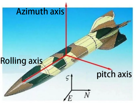
Case 2: Application of gyroscope in short-range guidance Gyroscopes are widely used in the field of artillery guidance, mainly used for tasks such as navigation, stability control and target tracking. The following are some application cases of MEMS gyroscopes in the field of short-range guidance: 1. Missile guidance system: MEMS gyroscopes are used in missile guidance systems to help the missile maintain a stable flight path and adjust the flight angle to track the target. These gyroscopes are typically used to measure the missile's rotation speed and direction in order to adjust the missile's course in real time. 2. Artillery shells and rocket guidance: In the short-range guidance of artillery shells and rockets, MEMS gyroscopes are used to measure the rotation and tilt of the ballistics to ensure that the warhead accurately hits the target.
|