


Copyright © Breeze Co.,Ltd Introduction All rights reserved. Site Map
- +86571-56076080
- sales@memsmag.com
- Room B3250, 3rd Floor, Building 1 (North), No. 368 Liuhe Road, Puyan Street, Binjiang District, Hangzhou

Industrial grade inertial sensor products
Application scenarios and solutions
K. Human-machine navigation The human-machine navigation and positioning work is mainly completed by the integrated positioning and directional navigation system. The integrated navigation system outputs position and attitude information in a real-time closed-loop, provides accurate direction reference and position coordinates, and at the same time predicts the aircraft status based on the attitude information in real time. |
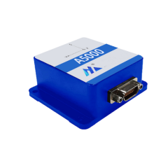
Case 1: A5000 - 9-axis AHRS attitude and orientation reference system integrated human-machine navigation in robots The "Asia-Pacific College Student Robot Competition Domestic Selection Event" has been successfully held for six times to select China's domestic robot-making champion team to compete for the Asia-Pacific crown. A college student from Beijing University of Posts and Telecommunications used AHRS to measure the posture of the robot in three axes, and finally entered the competition for the final championship. HANGZHOU MICRO-MAGIC TECHNOLOGY CO., LTD.’s A5000 is an excellent miniature AHRS product for measuring attitude and heading. Its internal processor has low power consumption and small output heading angle drift; it also provides calibrated three-dimensional acceleration, angular velocity and magnetic field strength. It is a measurement product with excellent performance for the stabilization and control of cameras, robots, vehicles and other series of equipment. For detailed technical specifications of this product, please refer to the product description.
Product installation method: Since there is a magnetic sensor inside the sensor, it is recommended to stay at least 30cm away from ferromagnetic materials during installation. The installation screws should be made of copper or aluminum, and a shock absorbing device should be added.
A5000's 9-axis attitude and orientation reference system, three-axis (gyro, accelerometer, magnetometer) and temperature sensor, accurate attitude measurement in harsh environments of motion and vibration, high-performance drift stability, 200HZ update frequency, wide temperature range: - 40℃~+85℃, output interface: TTL/RS232/RS485/RS422, etc. optional. |
Case 2: IMU (Inertial Measurement Unit) navigation control in underwater robots Underwater robots, also known as unmanned remotely operated submersibles, are robots used for extreme underwater operations. This kind of robot is often used in harsh and dangerous underwater environments or in situations that the human body cannot reach. The invention and application of underwater robots have brought possibilities to applications such as underwater object detection, underwater photography, underwater breeding, underwater detection, and underwater scientific research. Since it is an unmanned underwater operation, in addition to an automatic control system, an underwater communication system and a water environment detection system, the underwater robot must also have a precise navigation and positioning system. Among them, the electronic compass plays an important role in determining the heading of the underwater robot.
During the operation of underwater robots, their movements usually need to be controlled and adjusted through automatic control systems and communication systems so that they can reach the correct operating location. To ensure that the robot can successfully reach its destination, the underwater position must be monitored and adjusted. Among them, the robot's sonar can be used to detect obstacles and approaching objects to avoid collisions during underwater navigation. The GPS positioning system is used to measure the real-time coordinate position of the underwater robot. The electronic compass can measure the robot's azimuth navigation and send its own heading to the control system to compare with the destination location and make corresponding navigation. Adjustment. Especially when working remotely, the measurement of heading is even more important.
Maixinminwei's U3000 is a high-performance IMU module product that uses MEMS process technology and related calibration algorithms, making the product extremely precise in heading measurement accuracy. Our company has many years of experience in R&D and manufacturing of heading sensor products. The product has stable and reliable measurement values, low power consumption and small size. It is a popular product that can meet various measurement requirements. |
Case 3: IMU installed on AGV car for precise positioning Normally, when we use AGV cars, we will preset the driving path of the AGV car in advance, and then use instructions to let the AGV car go to the predetermined work station to complete the transportation work. The AGV car is equipped with an IMU to achieve positioning. What are the benefits of this positioning method? Woolen cloth? After the IMU is installed on the AGV car, a positioning device is installed at the main site. The AGV car uses the calculation of the IMU deviation signal and the collection of the ground positioning block signal to determine the position and direction of its own body. Finally, the speed and position are obtained through integration and calculation, and then From arrival to the purpose of navigation and positioning of the vehicle. The AGV car can achieve precise docking at the workstation by installing an IMU.
The technical method of installing IMU on AGV cars to achieve positioning was applied earlier. This technology is mature and highly flexible, allowing the AGV cars to have higher positioning accuracy, easy combination and compatibility, and a wide range of applications. The precise positioning of AGV trolleys is very important for transporting materials. Only accurate parking can ensure the production rhythm, and seamless connection can truly realize the automated transportation process. The precise positioning of AGV trolleys is an important link in logistics transportation. |
Case 4: Application of inclination sensor in robots A robot is a machine device that performs work automatically. It can accept human command, run pre-programmed programs, and act according to principles and programs formulated with artificial intelligence technology. Its mission is to help replace human jobs, such as manufacturing, construction, or dangerous jobs. The inspection robot is one of them. It carries a visible light camera, an infrared thermal imager, a pickup, an ultrasonic wave, an inclination sensor, etc. It also uses trajectory navigation to autonomously or remotely control outdoor high-voltage equipment according to optimal path planning. Patrol. Through machine vision, infrared temperature measurement, sound detection and other methods, the inspection robot can collect infrared thermal images, images, audio and other information of the equipment, and automatically identify the equipment's thermal defects, abnormal appearance, switch or switch position, and instrumentation. readings, oil level gauge position, etc., generate unified and standardized alarm matters and inspection reports, issue alarm information to operators, and provide basic data for equipment status maintenance. In unattended substations or smart substations with few people on duty, especially in geographical conditions such as plateaus, hypoxia, high cold, or severe weather conditions, inspection robots can replace or assist manual inspections of substation equipment.
When the inspection robot crosses obstacles, the deflection moment generated by the mass eccentricity destroys the horizontal posture of the robot body. In order to ensure that it moves forward smoothly, a simple and reliable center of mass adjustment method is needed. The inclination sensor is used to measure the inclination angle between the robot body and the horizontal plane, thereby controlling the movement of the counterweight moving motor and adjusting the center of mass of the robot to be suspended overhead. On the arm on the ground line, the measurement angle should be controlled within the range of 90° with an accuracy of ±0.1°. This ensures that the robot body maintains a horizontal posture and the arm that needs to be taken off or on the line completes the corresponding actions. Finally, the feasibility of the center of mass adjustment control method was verified through simulation experiments. |